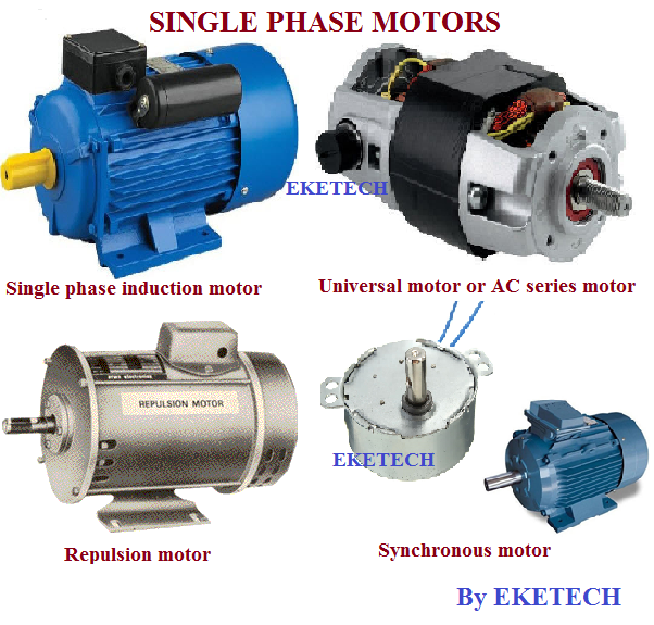
Single phase motors
As the name suggests, these are motors used on single phase supply. They are the most common types of electric motors with a wide range of applications and are manufactured in small fraction kilowatt ratings.
Their application ranges from domestic, commercial, to industrial applications. Examples of domestic applications are in fans, washing machines, mixers,
hair driers etc.
Classification of single phase induction motors
Single phase motors are classified into the following types:
- Single phase induction motor
- AC series motor (universal motor)
- Repulsion motor
- Synchronous motor
A single phase induction motor has two main parts. Namely: the stator and the rotor this is shown in the figure below.
Operating principle of single phase induction motors
Note: Single phase motors are not self starting.
When a single phase AC supply is applied to the stator, current flows through the stator conductor which then creates an alternating magnetic field around it. This magnetic field ( flux) produced, induces a current in the rotor which also produces an alternating magnetic field. Despite the production of these magnetic fields, the rotor does not rotate. This is because the magnetic field does not rotate but only alternates. Hence, no torque is produced to rotate the rotor. So, a rotating magnetic field is necessary to produce a resultant torque to rotate the rotor like in the case of 3 phase induction motors when supplied by 3 phase supply.
When a single phase AC supply is applied to the stator, current flows through the stator conductor which then creates an alternating magnetic field around it. This magnetic field ( flux) produced, induces a current in the rotor which also produces an alternating magnetic field. Despite the production of these magnetic fields, the rotor does not rotate. This is because the magnetic field does not rotate but only alternates. Hence, no torque is produced to rotate the rotor. So, a rotating magnetic field is necessary to produce a resultant torque to rotate the rotor like in the case of 3 phase induction motors when supplied by 3 phase supply.
So, the main reason why single phase motors are not self starting is because when supplied, they produce a magnetic field which does not rotate but only alternates ( alternating magnetic field).
This behavior is explained by the double field revolving theory.
This behavior is explained by the double field revolving theory.
Double field revolving theory
This theory states that any alternating magnetic field can be resolved in to two components with their magnitude being half the maximum magnitude of the alternating field, and the two resolved components rotate in opposite direction.So, applying this to the single phase motor, the alternating magnetic field produced as stated above, can be resolved into two equal component having the same magnitude but rotate in opposite direction.
 |
So if a squirrel cage rotor is placed in this field , equal and opposite forces and torque acts on the rotor (in opposite directions) as shown in the figure down. Hence, the rotor will only vibrate, but not rotate.
The two resolved components, each have a magnitude which is half the maximum magnitude of the alternating magnetic field as shown below.
By EKETECH.
Remained connected for interesting posts. Thanks.


