social

pop

What is Touch Potential?

What is Touch potential?

You often came across the term step and touch potential, but you never new what's all about. Grab it now.

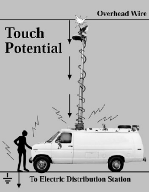
Touch potential is the potential generated across a conductive body or object to the earth, when the conductive body contacts or touches a live wire. So, current flow through the conductive body from the live wire to the earth. 
This can occur due to earth failure and inappropriate earthing in an installation. Other causes exist.
To illustrate this, we are going to see some common examples.

How touch potential is generated

1) A person touching a poorly earthed conductive part during earth failure. E.g touching the metallic part of towers, machines, etc during earth failure.
What is Touch potential


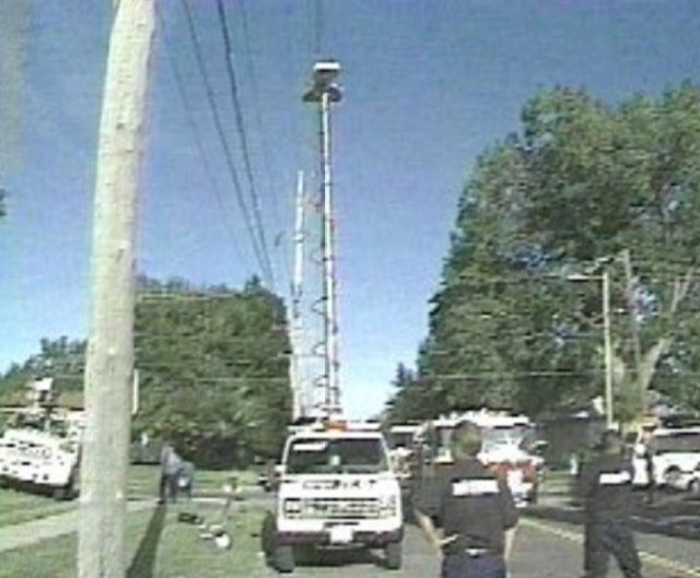
2) Live TV media antenna buses mistakenly touching live wires in transmission lines.
Touch potential

Touch potential


3) Excavators and lifters mistakenly touching a transmission line
Touch potential

Those are just some few examples of how touch potential is generated.
So, electrical technicians must be
ware of touch potential when working. Otherwise they may receive an electric shot and burns which can led to several damages and even death.

Related:

What is step potential?


Popular posts from this blog

GCE QUESTIONS AND SOLUTIONS FOR ELECTRICAL POWER SYSTEMS

 DOWNLOAD GCE PAST QUESTIONS AND SOLUTIONS FOR EPS POWER ELECTRONICS  Download 1     Download 1b Download 2     Download 2b      Download 2C Download 3 AUTOMATIC CONTROL OF ELECTRICAL MACHINES Download 1 Download 2 Download 3      Download 3b Download 4      Download 4b    2020 DESIGN OF ELECTRICAL INSTALLATION Download 1 Download 2 Download 3      Download 3b      Download 3C      Download 3D CIRCUIT ANALYSIS Download 1 Download 2 Download 3 Download 4 ENGINEERING SCIENCE Download 1 2019 Download 2 2023 paper 1 Download 3   MOCK      Download 3B  Download 4         Download 5          Download 6 Download 7   ITV ELECTRICAL AND ELECTRONIC CIRCUIT  Download 1 ELECTRICAL DIAGRAM Download 1   CAP ELECTRICAL TECHNOLOGY AND DIAGRAM Download 1 Download 2   ITV ELECTRICAL POWER SYSTEMS SOLUTIONS Download Solutions ELECTRICAL MACHINES  Download 1  ITV Download 2   MOCK Download 3   EE4 ENGINEERING DRAWING Download 1 ITV SOLUTIONS CIRCUIT THEORY Download 1

Download GCE syllabus | scheme of work all subjects

GCE syllabus secondary education Cameroon  570 Mathematics ♻️DOWNLOAD 570 Math 📲 575 Additional Mathematics ♻️DOWNLOAD Additional Mathematics📲 775 Further Math 🆓 Download Further Mathematics📲 Physics Ordinary Level 🆓 Download Physics Ordinary Level 📲 Physics Form 3-5 🆓 Download Physics Form 3 to Form 5 📲 Physics New Form 1 to 2 🆓Download Physics Form 1 and 2 📲 530 English Language 🆓 Download English Language 📲 540 Food and Nutrition 🆓DOWNLOAD FOOD AND NUTRITION 📲 545 French 🆓DOWNLOAD FRENCH 📲 590 Logic 🆓 LOGIC 📲 Chemistry Form 1 to Upper Six 🆓 DOWNLOAD CHEMISTRY Form 1 to U6📲 Chemistry Second Cycle 🆓Download CHEMISTRY Second Cycle📲 Geography  🆓DOWNLOAD GEOGRAPHY 📲 Geography Form 3-5 🆓DOWNLOAD GEOGRAPHY Form 3 to 5📲 History, Geography, Citizenship Form 1-2 🆓Download HISTORY, Geography, CITIZENSHIP📲 Geology 🆓Download  GEOLOGY 📲

GCE Advanced Level Past Questions Power Electronics

  GCE Advanced Level Past Questions   Technical and Vocational Education Examinations Electrical Power Systems EPS Power Electronics Specialty Name (Specialty Code) Electrical Power Systems EPS (F3) Subject Title   Power Electronics Paper Nº   2 Subject Code Nº 7235  1.  Control of a D.C motor          The circuit shown in figure 1, include the control and the power circuit of a DC motor to make the up and down movements of a system. All the OP-AMP and switches are ideal a)   Study of the control circuit (OA1; R’s and (AO2). i)       Give the operating mode of the operational amplifiers (OA1; R’s) and (AO2).                  ( 6 marks) ii)      prove that the expression of the voltage at the OA1  inverting input terminal in function of V 1  and V 01  is  V- = ( V 1  + V 01 ) / 2         (6 marks) iii) Prove that the expression of the voltage a