social

pop

Design of an industrial sorting and counting machine | Olome Baudouin Ekute University of Bamenda

Design and realization of an automatic industrial sorting and counting machine

In order to present this project, this dissertation is divided into five chapters.
  •  Chapter 1: General introduction of the system.
  • Chapter 2: Review of related literature on the project and contents related to the project.
  • Chapter 3: Technological study of components (theoretical study, dimensioning of components and choice criterion).
  • Chapter 4: System simulation and practical implementation.
  • Chapter 5: Difficulties encountered, recommendations, future scope, and conclusion.

Get complete PDF, simulation, codes, and PCB design. Link at bottom

Problem statement 

In modern industry, the sorting of items or products into various categories by an automated system is of great importance in order to have competitive advantages in production speed, efficiency, production value and labour cost.
This project involves designing and realizing an automated industrial sorting machine which is able to sort and count the number of items into their various categories. For example, in an industry producing soaps of different sizes, the sorting machine can be used to group these soaps into their various categories.

Scope and objectives of the study

The objectives of this project is:
  • Sorting of two items on the basis of their respective height. With the height of the smaller item ranging from 3.5cm to 9cm and the bigger item ranging from 9.1cm to 20cm.
  • Counting the number of items sorted.
Using a PIC 16F877A microcontroller to implement the control of this system.

Overview

The machine consist of a conveyor belt which carries the items from the manufactured end, passing through a detector made of IR sensors which detects the category of the item. The item is then passed to the sorting compartment designed at one end of the conveyor belt in order for the items to be sorted. Once at the sorting compartment of the conveyor belt, the item is sorted into its category. The sorting is done with the use of two DC motor controlled linear arm actuators each corresponding to a specific category of item. The linear actuator which ejects in a single axes directs the item through a specific route into the next process or receptor. An LCD is used to display the number of items being sorted.

System block diagram
sorting and counting machine block diagram
System block diagram

Components used

The components used in designing this system are:
  • PIC microcontroller
  • Infra-red sensors
  • DC Motors
  • Motor driver
  • Liquid crystal display
  • Resistors, capacitors, diodes, etc.
  • Conveyor belt structure (Plastic belt, bearings, roller pipes, wooden/metallic framework)

Dimensioning of system components

Available in complete PDF

Flow chart 
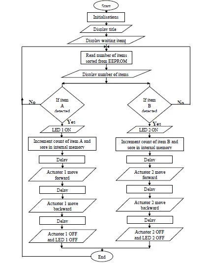
sorting and counting machine flow chart
System flow chart

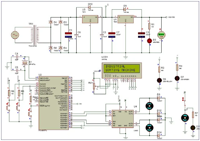
Circuit diagram and System simulation

Complete simulation, codes PCB design available. Check at bottom
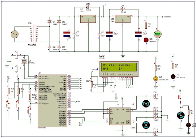
sorting machine circuit diagram
sorting and counting machine circuit diagram
Circuit diagram

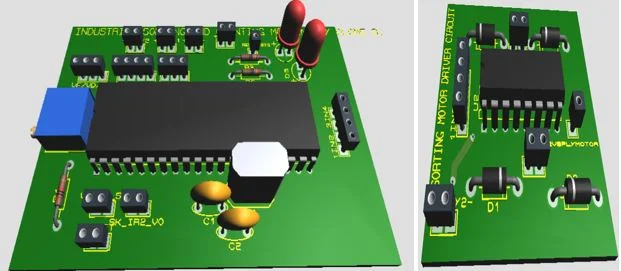
Realised piece

sorting and counting machine PCB design

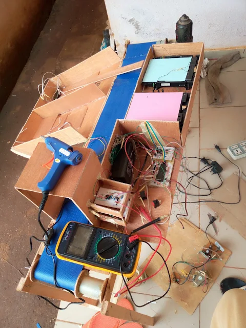
industrial sorting and counting machine
Industrial sorting and counting machine
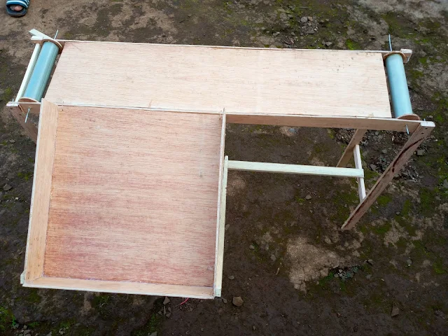
small conveyor belt frame

Click Here to get complete PDF, simulation, code and PCB design

Reference: Olome B.E. "design and realisation of an automatic industrial sorting machine", university of Bamenda, July 2019
Popular posts from this blog

GCE QUESTIONS AND SOLUTIONS FOR ELECTRICAL POWER SYSTEMS

 DOWNLOAD GCE PAST QUESTIONS AND SOLUTIONS FOR EPS POWER ELECTRONICS  Download 1     Download 1b Download 2     Download 2b      Download 2C Download 3 AUTOMATIC CONTROL OF ELECTRICAL MACHINES Download 1 Download 2 Download 3      Download 3b Download 4      Download 4b    2020 DESIGN OF ELECTRICAL INSTALLATION Download 1 Download 2 Download 3      Download 3b      Download 3C      Download 3D CIRCUIT ANALYSIS Download 1 Download 2 Download 3 Download 4 ENGINEERING SCIENCE Download 1 2019 Download 2 2023 paper 1 Download 3   MOCK      Download 3B  Download 4         Download 5          Download 6 Download 7   ITV ELECTRICAL AND ELECTRONIC CIRCUIT  Download 1 ELECTRICAL DIAGRAM Download 1   CAP ELECTRICAL TECHNOLOGY AND DIAGRAM Download 1 Download 2   ITV ELECTRICAL POWER SYSTEMS SOLUTIONS Download Solutions ELECTRICAL MACHINES  Download 1  ITV Download 2   MOCK Download 3   EE4 ENGINEERING DRAWING Download 1 ITV SOLUTIONS CIRCUIT THEORY Download 1

Download GCE syllabus | scheme of work all subjects

GCE syllabus secondary education Cameroon  570 Mathematics ♻️DOWNLOAD 570 Math 📲 575 Additional Mathematics ♻️DOWNLOAD Additional Mathematics📲 775 Further Math 🆓 Download Further Mathematics📲 Physics Ordinary Level 🆓 Download Physics Ordinary Level 📲 Physics Form 3-5 🆓 Download Physics Form 3 to Form 5 📲 Physics New Form 1 to 2 🆓Download Physics Form 1 and 2 📲 530 English Language 🆓 Download English Language 📲 540 Food and Nutrition 🆓DOWNLOAD FOOD AND NUTRITION 📲 545 French 🆓DOWNLOAD FRENCH 📲 590 Logic 🆓 LOGIC 📲 Chemistry Form 1 to Upper Six 🆓 DOWNLOAD CHEMISTRY Form 1 to U6📲 Chemistry Second Cycle 🆓Download CHEMISTRY Second Cycle📲 Geography  🆓DOWNLOAD GEOGRAPHY 📲 Geography Form 3-5 🆓DOWNLOAD GEOGRAPHY Form 3 to 5📲 History, Geography, Citizenship Form 1-2 🆓Download HISTORY, Geography, CITIZENSHIP📲 Geology 🆓Download  GEOLOGY 📲

GCE Advanced Level Past Questions Power Electronics

  GCE Advanced Level Past Questions   Technical and Vocational Education Examinations Electrical Power Systems EPS Power Electronics Specialty Name (Specialty Code) Electrical Power Systems EPS (F3) Subject Title   Power Electronics Paper Nº   2 Subject Code Nº 7235  1.  Control of a D.C motor          The circuit shown in figure 1, include the control and the power circuit of a DC motor to make the up and down movements of a system. All the OP-AMP and switches are ideal a)   Study of the control circuit (OA1; R’s and (AO2). i)       Give the operating mode of the operational amplifiers (OA1; R’s) and (AO2).                  ( 6 marks) ii)      prove that the expression of the voltage at the OA1  inverting input terminal in function of V 1  and V 01  is  V- = ( V 1  + V 01 ) / 2         (6 marks) iii) Prove that the expression of the voltage a