Voltage regulator
A voltage regulator is one of the most widely used electronic device in
an electronic circuit. Its main function is to keep the terminal voltage of the
DC supply constant. A regulated voltage (no fluctuations and noise levels) is
very important for smooth functioning of electronic devices. A non-regulated
voltage will cause an electronic circuit or device to function abnormally due
to unacceptable variations of the signals.
There exist two main types of voltage regulators; the linear voltage
regulator and the switching voltage regulator. Our interest here is
with the integrated circuit (IC) based voltage regulator which can be of linear
type or switching type seen below.
1) Linear voltage regulator
Linear regulators are step-down converter system used to maintain a
steady voltage. In a linear voltage regulator, the resistance of the regulator
varies with respect to the load. The variable conductivity of the active pass
element (usually a bipolar junction transistor or a metal oxide semi-conductor
field effect transistor) is responsible for regulating the constant output
voltage.
When a load is connected, a change in either input voltage or variation
of the load will result in a variation in current through the transistor to
maintain the constant output. The transistor must operate in the active or ohmic
region (linear region) in order to vary its current (collector-emitter current
in case of BJT). Linear voltage regulators are usually classified into the
fixed voltage regulator and adjustable voltage regulator seen below.
a) Fixed voltage regulators
These voltage regulators provide a fixed or constant output voltage. A
fixed voltage regulator can be a positive voltage regulator or a negative
voltage regulator.
 |
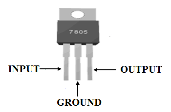
| A 5V voltage regulator (7805) |
The positive voltage regulator provides a constant positive output
voltage. IC’s in the 78XX series are positive fixed voltage regulators. By
convention, the XX denotes the regulated output voltage. For example the IC
7805 provides a constant output voltage of +5V.
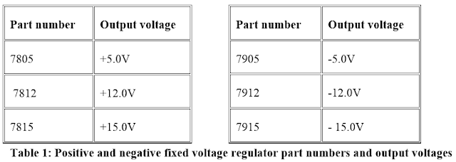
A negative fixed voltage
regulator is similar to the positive fixed voltage regulator in design,
construction and operation. The only difference is in the polarity of output
voltages which is negative. These IC’s are in the 79XX series. Fox example See
the table below.
b) Adjustable voltage regulators
An adjustable voltage regulator is a kind of voltage regulator whose
regulated output voltage can be varied over a range. There exist two types; the
positive adjustable voltage regulator and negative adjustable regulator. An
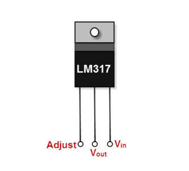
example of the positive adjustable voltage regulator is the LM317, whose output
voltage can be varied in the range of 1.2V to 57V. LM337 is an example of a
negative adjustable voltage regulator which is a complement of the LM317 i.e.
having a negative adjustable output voltage.
 |
| An Adjustable voltage regulator (e.g LM317) |
2) Switching voltage regulator
Switching voltage regulators
differ in design, construction and operation compared to linear voltage
regulators. In switching regulators the output voltage is regulated by
controlling the switching time of feedback circuitry that is by adjusting the
duty cycle (ON time) of the pass transistor.
The output voltage can be higher or less than the input voltage.
 |
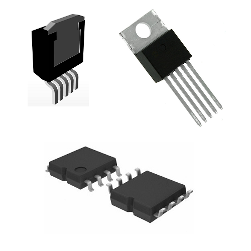
| Switching voltage regulator |
Ref:
Olome Baudouin E. "Design and realization of an automatic industrial sorting machine", University of Bamenda, July 2019.
Htttp://en.m.wikipedia.org/wiki/linear_regulator
Htttp://www.google.com/amps/s/www.electronicshub.org/types-of-voltage-regulators/%3famp
