social

pop

Types of Infrared Sensors

Types of IR Sensors

Infrared sensors can be classified into passive or active infrared sensors.

1) Passive infrared sensor

These are IR sensors which do not have an infrared source but detects energy emitted by obstacles. They are of two types namely:
  • Thermal infrared sensor: use infrared energy as a source of heat and are independent of wavelength.
  • Quantum infrared sensor: The photo-sensitivity of quantum type detectors is dependent on the wavelength and are perform better than thermal infrared sensors.
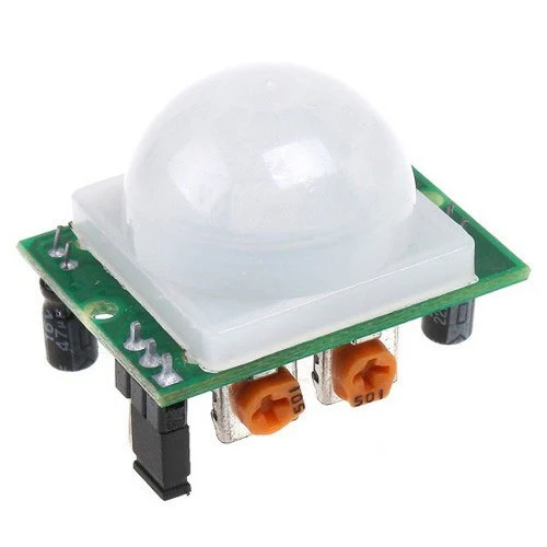
Passive infrared sensor

2) Active infrared sensors

These are IR sensors which contains an infrared source and infrared detector. The infrared source is an IR LED and the receiver can be a photodiodes or a phototransistors.
These sensors can be used in object sensing, obstacle avoidance robot, motion detectors, measurement of distance, smoke detection etc.


The figure below show a typical photodiode infrared sensor.
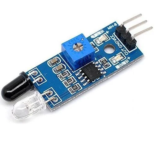
types of infrared sensors
A typical infrared sensor


Olome Baudouin E. "Design and realization of an automatic industrial sorting machine", University of Bamenda, July 2019.

Working principles and applications of infrared sensors, Htttp://en.m.wikipedia.org,


Popular posts from this blog

GCE QUESTIONS AND SOLUTIONS FOR ELECTRICAL POWER SYSTEMS

 DOWNLOAD GCE PAST QUESTIONS AND SOLUTIONS FOR EPS POWER ELECTRONICS  Download 1     Download 1b Download 2     Download 2b      Download 2C Download 3 AUTOMATIC CONTROL OF ELECTRICAL MACHINES Download 1 Download 2 Download 3      Download 3b Download 4      Download 4b    2020 DESIGN OF ELECTRICAL INSTALLATION Download 1 Download 2 Download 3      Download 3b      Download 3C      Download 3D CIRCUIT ANALYSIS Download 1 Download 2 Download 3 Download 4 ENGINEERING SCIENCE Download 1 2019 Download 2 2023 paper 1 Download 3   MOCK      Download 3B  Download 4         Download 5          Download 6 Download 7   ITV ELECTRICAL AND ELECTRONIC CIRCUIT  Download 1 ELECTRICAL DIAGRAM Download 1   CAP ELECTRICAL TECHNOLOGY AND DIAGRAM Download 1 Download 2   ITV ELECTRICAL POWER SYSTEMS SOLUTIONS Download Solutions ELECTRICAL MACHINES  Download 1  ITV Download 2   MOCK Download 3   EE4 ENGINEERING DRAWING Download 1 ITV SOLUTIONS CIRCUIT THEORY Download 1

Download GCE syllabus | scheme of work all subjects

GCE syllabus secondary education Cameroon  570 Mathematics ♻️DOWNLOAD 570 Math 📲 575 Additional Mathematics ♻️DOWNLOAD Additional Mathematics📲 775 Further Math 🆓 Download Further Mathematics📲 Physics Ordinary Level 🆓 Download Physics Ordinary Level 📲 Physics Form 3-5 🆓 Download Physics Form 3 to Form 5 📲 Physics New Form 1 to 2 🆓Download Physics Form 1 and 2 📲 530 English Language 🆓 Download English Language 📲 540 Food and Nutrition 🆓DOWNLOAD FOOD AND NUTRITION 📲 545 French 🆓DOWNLOAD FRENCH 📲 590 Logic 🆓 LOGIC 📲 Chemistry Form 1 to Upper Six 🆓 DOWNLOAD CHEMISTRY Form 1 to U6📲 Chemistry Second Cycle 🆓Download CHEMISTRY Second Cycle📲 Geography  🆓DOWNLOAD GEOGRAPHY 📲 Geography Form 3-5 🆓DOWNLOAD GEOGRAPHY Form 3 to 5📲 History, Geography, Citizenship Form 1-2 🆓Download HISTORY, Geography, CITIZENSHIP📲 Geology 🆓Download  GEOLOGY 📲

GCE Advanced Level Past Questions Power Electronics

  GCE Advanced Level Past Questions   Technical and Vocational Education Examinations Electrical Power Systems EPS Power Electronics Specialty Name (Specialty Code) Electrical Power Systems EPS (F3) Subject Title   Power Electronics Paper Nº   2 Subject Code Nº 7235  1.  Control of a D.C motor          The circuit shown in figure 1, include the control and the power circuit of a DC motor to make the up and down movements of a system. All the OP-AMP and switches are ideal a)   Study of the control circuit (OA1; R’s and (AO2). i)       Give the operating mode of the operational amplifiers (OA1; R’s) and (AO2).                  ( 6 marks) ii)      prove that the expression of the voltage at the OA1  inverting input terminal in function of V 1  and V 01  is  V- = ( V 1  + V 01 ) / 2         (6 marks) iii) Prove that the expression of the voltage a