social

pop

L293D Motor Driver

L293D

The L293D is a 16 pin motor driver integrated circuit used to drive motors. It consists of two H-bridge embedded in a single chip. The L293D is capable of running two DC motors independently and also able to reverse or change the direction of rotation of the motor. The IC can supply a motor with operating voltage of up to 36V with a current .
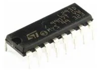
L293D motor driver
L293D motor driver


Pin1 (
Enable 1,2): Enables input 1 and input 2. So when high, left part of the IC is enabled and when low left part is disabled
Pin2 (Input 1)when high, current flows through output 1
Pin3 (Output 1): Connected to one terminal of the motor, M1
Pin4 (Ground): Connect to the ground
Pin5 (Ground): Connect to the ground
Pin6 (Output 2): Connected to the other terminal of the motor, M1
Pin7 (Input 2): When high, current flows through output 2
Pin8 (Vcc2 (Vs)): Voltage to be supplied to the motor
Pin9 (Enable 3,4): Enables input 3 and input 4. So when high, right part of the IC is enabled and when low right part is disabled
Pin10 (Input 3): When high current flows through output 3
Pin11 (Output 3): Connected to one of the terminals of motor, M2
Pin12 (Ground): Connect to the ground
Pin13 (Ground): Connect to the ground
Pin14 (Output 4): Connected to the other of the terminal of motor, M2
Pin15 (Input 4): When high current flows through output 4
Pin16 (Vcc2 (Vss)): Voltage to supply to the IC 
Summary table
The pin configuration of the L293D IC is shown in the table below.
L293D pin configuration


Reference: Olome Baudouin E. "Design and realization of an automatic industrial sorting machine", University of Bamenda, July 2019.

Related and Recommended:


Popular posts from this blog

How to Install Proteus 8 Professional: A Step-by-Step Guide

 How to Install Proteus 8 Professional: A Step-by-Step Guide Proteus 8 Professional is a powerful tool for electronic circuit design and simulation. Whether you’re a student, hobbyist, or professional engineer, following a clear installation process ensures you get started without headaches. Are you ready to start designing and simulating electronic circuits with Proteus 8 Professional!   Here’s a comprehensive, guide to installing Proteus 8 Professional on your Windows PC. Step 1: Download the Installer ·        Visit the official Labcenter Electronics website or another trusted source to download the Proteus 8 Professional installer. Avoid unofficial sources to prevent malware or corrupted files . You can download from HERE DOWNLOAD PROTEUS AND ARDUINO ·        The installer typically comes as a ZIP file. Wait for the download to finish and locate it in your Downloads folder Step 2: Extract the Installer...

Download HND Past Questions and Solutions

Download Cameroon HND Past Questions & Solutions Boost your exam prep with past papers and answers across all fields! How to Access Past Questions Visit the Cameroon HND Platform or trusted sites like EKETECH . Browse by field : Select your program (e.g., Civil Engineering , Banking and Finance , Nursing ). Download PDFs for free or via subscription. Practice with solutions : Review answers to refine your understanding. Fields of Study Covered Past questions are available for all HND programs in Cameroon, including: Engineering Civil Engineering Design Software Engineering Electrical Power Systems Telecommunication Mechanical Engineering Computer Engineering Medical Sciences Nursing Medical Laboratory Studies Health Care Management Physiotherapy Nutrition and Dietetics Agriculture Agribusiness Management Agricultural Engineering Food Technology Integrated Agriculture Business Accounting Banking and...

Intermediate switch connection and wiring diagram

Intermediate switch An intermediate switch is a switch which permits the control of a lighting point from three positions. In order to control this lighting point from the three positions, the intermediate switch is connected together with two other 2-way switches. Application: it can be used in lighting a room or hall having 3 entrances , it can also be used in long corridors and staircases. We shall be looking at these connections. Connection diagram of intermediate switching Below is an illustration of the connection. The brown lines indicated on the diagram are the switching contacts. The switch labelled 2 is an intermediate switch . The figure below is the configuration of an intermediate switch. The switch labelled 1 and 3 in the first diagram are two-way switches.  Click here to know more about two-way switches . ON and OFF positions of intermediate switching ON positions OFF positions Staircase wiring layout using an inte...