social

pop

Conveyor belt | Conveyor systems | Types of conveyor belts

Conveyor systems and conveyor belts

There are two main industrial classes of conveyor systems; 
  • Those used in general material handling such as moving boxes along in a factory.
  • Those used in bulk material handling such as transporting industrial and agricultural materials or products, such as grain, coal, ores, etc. they are generally used in outdoor locations.

Conveyor belts

Conveyor belts were used since the 19th century. In 1892, Thomas Robins began a series of inventions which led to the development of a conveyor belt used for carrying coal, ores and other products.
In general, a conveyor belt consists of two end pulleys, with a continuous loop of material that rotates round these pulleys. The pulleys are used for providing the drive to the belt through a drive unit gear box powered by an electric motor. The forward movement of the belt is as a result of the friction generated between the pulley and the belt. One or both of the pulleys can be powered and it also helps to provide proper tension to the belt.
The powered pulley is called the drive pulley while the un-powered pulley is called the idler. Most of the belts in material handling is made of two layers, the top layer called the carcass which provides linear strength and shape and the bottom layer called the cover. The carcass is often a can be made from materials like cotton, plastic web or roots and mesh. The cover can be made from rubber or plastic compounds.
Nowadays, the material used for making a conveyor belt is determined by its application and can be made from materials like PVC, cotton, canvas, leather, polyester, neoprene, nylon, urethane, polyurethane, rubber, silicone and steel are commonly used in conveyor belts. The figure below shows an example of a conveyor belt.
conveyor belt
A view of a belt conveyor
There exist a variety of belt conveyors which are used depending on the domain of application. They include the:
  • wire belt conveyor
Wire belt conveyor

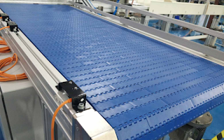
  • plastic belt conveyor
Plastic conveyor belt

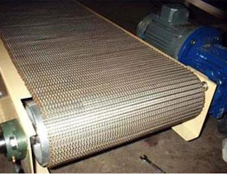
  • wire mesh conveyors
Wire mesh conveyor

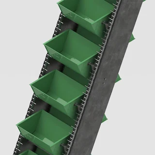
  • bucket Conveyor
Bucket conveyor

  • spiral conveyors
Spiral conveyor

  • pneumatic conveyors

  • screw conveyor or auger conveyor

  •  etc.
These conveyor belts may be of roller, flat, modular, cleated, curved or  inclined type.
Reference:
[1] Olome Baudouin E. "Design and realization of an automatic industrial sorting machine", University of Bamenda, July 2019.
[2] International journal of advanced research in science and engineering vol no. 07, special        issues no.01 march 2018

Popular posts from this blog

How to Install Proteus 8 Professional: A Step-by-Step Guide

 How to Install Proteus 8 Professional: A Step-by-Step Guide Proteus 8 Professional is a powerful tool for electronic circuit design and simulation. Whether you’re a student, hobbyist, or professional engineer, following a clear installation process ensures you get started without headaches. Are you ready to start designing and simulating electronic circuits with Proteus 8 Professional!   Here’s a comprehensive, guide to installing Proteus 8 Professional on your Windows PC. Step 1: Download the Installer ·        Visit the official Labcenter Electronics website or another trusted source to download the Proteus 8 Professional installer. Avoid unofficial sources to prevent malware or corrupted files . You can download from HERE DOWNLOAD PROTEUS AND ARDUINO ·        The installer typically comes as a ZIP file. Wait for the download to finish and locate it in your Downloads folder Step 2: Extract the Installer...

Intermediate switch connection and wiring diagram

Intermediate switch An intermediate switch is a switch which permits the control of a lighting point from three positions. In order to control this lighting point from the three positions, the intermediate switch is connected together with two other 2-way switches. Application: it can be used in lighting a room or hall having 3 entrances , it can also be used in long corridors and staircases. We shall be looking at these connections. Connection diagram of intermediate switching Below is an illustration of the connection. The brown lines indicated on the diagram are the switching contacts. The switch labelled 2 is an intermediate switch . The figure below is the configuration of an intermediate switch. The switch labelled 1 and 3 in the first diagram are two-way switches.  Click here to know more about two-way switches . ON and OFF positions of intermediate switching ON positions OFF positions Staircase wiring layout using an inte...

How to Draw A Three-Phase Waveform and Its Importance

How to Draw A Three-Phase Waveform and Its Importance  Learn how to easily draw a three-phase AC waveform step-by-step, a fundamental skill for power electronics and power systems engineers. Discover its critical role in efficient power delivery for industrial applications and renewable energy systems. Method 1: Easiest Triangular Wave Connection to draw a three phase wave form Sketch three identical triangular waves, each spanning 360° with linear rises from 0° to 90° (peak), falls to 180° (zero), dips to 270° (-peak), and returns to 360° (zero). Label them R (rise starts at 0°), Y (rise at 120°), and B (rise at 240°); connect their outer tips externally with straight lines to approximate a continuous three-phase waveform set. This quick method visually captures 120° phase shifts without curve drawing, ideal for fast teaching or power electronics sketches. Method 2: Standard Sine Wave Drawing Plot on a time (0°-360°) vs. voltage axis: draw R-phase as a full sine wave p...