Actuators and types of actuators
An actuator is a device that controls or moves mechanisms or systems by converting energy
into motion or force. This energy can be obtained from electric current, air or liquid. Actuators are used in diverse fields such as electrical and electronic engineering,
mechanical engineering. They produce either linear motion, circular (rotary)
motion or oscillatory motion and are used in many machinery for provide a
motion or force in processes such as braking, sorting, driving disk drives,
printing etc. One of the earliest uses of an actuator (pistons) was in steam
engines in the mid-1670s designed by a French physicist and inventor, Denis
Papin.
 |
| A block view of an actuator system |
Types of actuators
There exist four main types of actuators namely the:
·
Electric actuator
·
Mechanical actuator
·
Hydraulic actuator
·
Pneumatic actuator
a)
Electric actuator
An electric actuator is an electromechanical device that converts electrical energy into mechanical torque to provide motion
or force. The electrical energy is used
to create motion in equipment that require multi-turn valves like gate or globe
valves. They use electric motors which operate through the interaction of magnetic
fields and current-carrying conductors to generate force. There are many designs of electric actuators, with such designs depending
on the domain of application or on the system in which they need to be
utilized.
b)
Mechanical actuator
Mechanical actuators converts rotary motion to linear motion. Devices
used are gears, rails, pulley, chain etc. Some of the simple mechanisms used to
convert motion are screws, where the rotation of the actuator's nut causes the
screw shaft to move in a straight line, the wheel and axle, where the rotating
motion of a wheel causes a belt or something similar to move in a linear
motion.
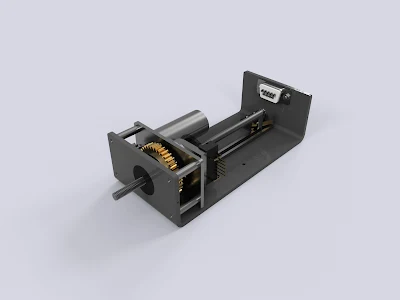
A combination of an electrical and mechanical actuator system is called an ELECTRO-MECHANICAL Actuator
A combination of an electrical and mechanical actuator system is called an ELECTRO-MECHANICAL Actuator
 |
| Electromechanical actuator |
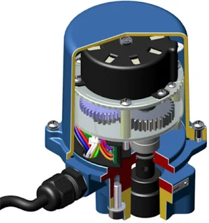
 |
| Electromechanical actuator |
 |
| mechanical actuator |
c)
Hydraulic actuator
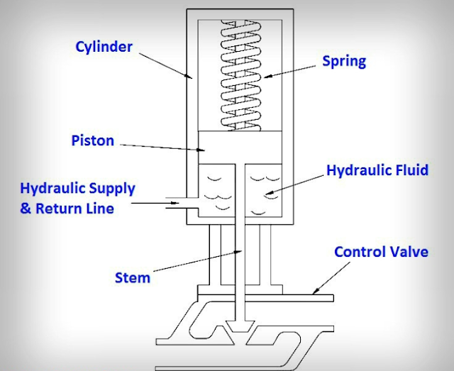
Hydraulic actuators consist of a cylinder or fluid motor that utilizes
hydraulic power to facilitate mechanical process.
The mechanical motion gives an output in terms of linear, rotary or oscillatory motion. Since liquids are nearly incompressible, they take longer to gain speed and power and also slow back down, but they can exert great force.
The hydraulic actuator also allows for very precise control of the movement produced. In linear hydraulic actuators, a typical setup is made up of a hollow cylinder that contains a liquid, usually oil, and a piston that is inserted in it. When pressure is applied onto the piston, objects can be moved by the force produced.
The mechanical motion gives an output in terms of linear, rotary or oscillatory motion. Since liquids are nearly incompressible, they take longer to gain speed and power and also slow back down, but they can exert great force.
 |
| Constitution of a hydraulic actuator |
The hydraulic actuator also allows for very precise control of the movement produced. In linear hydraulic actuators, a typical setup is made up of a hollow cylinder that contains a liquid, usually oil, and a piston that is inserted in it. When pressure is applied onto the piston, objects can be moved by the force produced.
 |
| Hydraulic actuator |
d) Pneumatic actuators
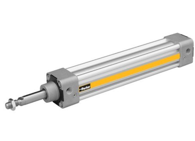
 |
| Pneumatic linear actuator |
Ref:
