social

pop

Interfacing a 16X4 LCD

Interfacing 16X4 LCD

Simulation is done with Proteus ISIS
code: MikroC
Requirements:
  • 16X4 LCD
  • PIC16F877A
  • 8 MHz oscillator
  • A variable resistor (5k)
  • 22pF capacitor
  • A resistor (10k)

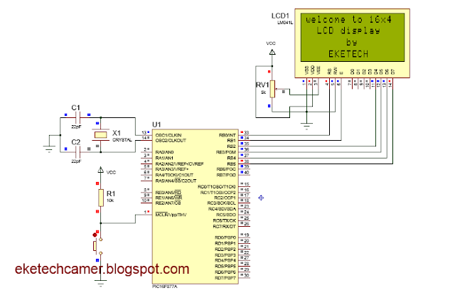
Circuit Diagram of 16X4 LCD and code is shown below


interfacing 16x4 LCD

 // Begin LCD configuration
sbit LCD_RS_direction at TRISB0_bit;
sbit LCD_EN_direction at TRISB1_bit;
sbit LCD_D4_direction at TRISB2_bit;
sbit LCD_D5_direction at TRISB3_bit;
sbit LCD_D6_direction at TRISB4_bit;
sbit LCD_D7_direction at TRISB5_bit;

sbit LCD_RS at RB0_bit;
sbit LCD_EN at RB1_bit;
sbit LCD_D4 at RB2_bit;
sbit LCD_D5 at RB3_bit;
sbit LCD_D6 at RB4_bit;
sbit LCD_D7 at RB5_bit;

// End of LCD configuration

void main()
{ char txt1[]="welcome to 16x4"; char txt2[]="LCD display";
  char txt3[]="by"; char txt4[]="EKETECH";

TRISB=0X00;   // Configure PORTB as output
PORTB=0X00;        // initialise PORTB
while(1)                           // loop
{
lcd_Init();                        //  initialise LCD
lcd_cmd(_lcd_clear);          //  clear LCD
lcd_cmd(_lcd_cursor_off); //OFF the cursor
delay_ms(100);           // delay for 0.1 second
lcd_out(1,1,txt1);               // display "welcome to 16x4" on row 1 of LCD
lcd_out(2,3,txt2);              // display "LCD display"; on row 2 column 3
delay_ms(200);             // delay for 0.2 second
lcd_out(3,4,txt3);        // display "by" on row 3 column 4 of LCD
delay_ms(200);          // delay for 0.2 second
lcd_out(4,1,txt4);                 // display "EKETECH"; on row 4 column 1
delay_ms(1500);                    // delay for 1.5 seconds

}
}

Click hereVideo

By EKETECH
Popular posts from this blog

GCE QUESTIONS AND SOLUTIONS FOR ELECTRICAL POWER SYSTEMS

 DOWNLOAD GCE PAST QUESTIONS AND SOLUTIONS FOR EPS POWER ELECTRONICS  Download 1     Download 1b Download 2     Download 2b      Download 2C Download 3 AUTOMATIC CONTROL OF ELECTRICAL MACHINES Download 1 Download 2 Download 3      Download 3b Download 4      Download 4b    2020 DESIGN OF ELECTRICAL INSTALLATION Download 1 Download 2 Download 3      Download 3b      Download 3C      Download 3D CIRCUIT ANALYSIS Download 1 Download 2 Download 3 Download 4 ENGINEERING SCIENCE Download 1 2019 Download 2 2023 paper 1 Download 3   MOCK      Download 3B  Download 4         Download 5          Download 6 Download 7   ITV ELECTRICAL AND ELECTRONIC CIRCUIT  Download 1 ELECTRICAL DIAGRAM Download 1   CAP ELECTRICAL TECHNOLOGY AND DIAGRAM Download 1 Download 2   ITV ELECTRICAL POWER SYSTEMS SOLUTIONS Download Solutions ELECTRICAL MACHINES  Download 1  ITV Download 2   MOCK Download 3   EE4 ENGINEERING DRAWING Download 1 ITV SOLUTIONS CIRCUIT THEORY Download 1

Download GCE syllabus | scheme of work all subjects

GCE syllabus secondary education Cameroon  570 Mathematics ♻️DOWNLOAD 570 Math 📲 575 Additional Mathematics ♻️DOWNLOAD Additional Mathematics📲 775 Further Math 🆓 Download Further Mathematics📲 Physics Ordinary Level 🆓 Download Physics Ordinary Level 📲 Physics Form 3-5 🆓 Download Physics Form 3 to Form 5 📲 Physics New Form 1 to 2 🆓Download Physics Form 1 and 2 📲 530 English Language 🆓 Download English Language 📲 540 Food and Nutrition 🆓DOWNLOAD FOOD AND NUTRITION 📲 545 French 🆓DOWNLOAD FRENCH 📲 590 Logic 🆓 LOGIC 📲 Chemistry Form 1 to Upper Six 🆓 DOWNLOAD CHEMISTRY Form 1 to U6📲 Chemistry Second Cycle 🆓Download CHEMISTRY Second Cycle📲 Geography  🆓DOWNLOAD GEOGRAPHY 📲 Geography Form 3-5 🆓DOWNLOAD GEOGRAPHY Form 3 to 5📲 History, Geography, Citizenship Form 1-2 🆓Download HISTORY, Geography, CITIZENSHIP📲 Geology 🆓Download  GEOLOGY 📲

GCE Advanced Level Past Questions Power Electronics

  GCE Advanced Level Past Questions   Technical and Vocational Education Examinations Electrical Power Systems EPS Power Electronics Specialty Name (Specialty Code) Electrical Power Systems EPS (F3) Subject Title   Power Electronics Paper Nº   2 Subject Code Nº 7235  1.  Control of a D.C motor          The circuit shown in figure 1, include the control and the power circuit of a DC motor to make the up and down movements of a system. All the OP-AMP and switches are ideal a)   Study of the control circuit (OA1; R’s and (AO2). i)       Give the operating mode of the operational amplifiers (OA1; R’s) and (AO2).                  ( 6 marks) ii)      prove that the expression of the voltage at the OA1  inverting input terminal in function of V 1  and V 01  is  V- = ( V 1  + V 01 ) / 2         (6 marks) iii) Prove that the expression of the voltage a